
ClukWorx – Smart Feeder
Why?
In 2020 – beyond my wildest expectations, I became a chicken farmer. Genuinely one of the most refreshing periods of my life and am very thankful for the opportunity to have gotten eye level with nature. Around 6 months after purchasing the first bird, I realized nights on the town and weekend trips were a thing of the past. It would likely stay that way without some form of help. Alas, like every other boom, the homesteading bubble popped when folks returned to work, and I found myself back working as an engineer and keeping the birds as a hobby more than anything. Never got around to actually building the feeder in 2020 – but I worked on designs and did research.
In 2025 – My wife and I found out she was pregnant. We already have 4 dogs we cook for nightly in addition to the birds, I work rotationally as a drilling fluid engineer meaning she’s on her own half the time, and now she would be doing all of this alone… while pregnant. We also have a mean rooster which has been getting quite froggy lately and I’ll be damned if my wife gets pecked to death by polish birds! After excitements settled I began working on the project I’d put off for years to make life easier.
What?
Let’s start with constraints.
Environment – High Humidity, Potential for Rain. We will need the electronics to be inside a splash proof enclosure with all terminations and and hardware sealed where possible. Pest and rodents entering from feed outlets, or removing tops must be considered. This will be a 3D printed project so the plastic material chose must have UV and exterior ratings available. We must also be safe for dry food.
Storage – Chicken feed sacks are 35-50lbs. Lets aim for 35lb bin size. We want gravity to work for us where possible – Food must be stored overhead.
Power – Most folks do not have power running to the coop. We need a way to charge the unit in steady state with solar panels, OR provide back-up power to allow an extension cord to be connected temporarily on a weekly/monthly basis. The selected battery – 14.4V 5A 6600 Ah LiFe4Po with BMS provides approximately 1 month of run time at heavy usage, and has high enough output to power the motor and PLC. We will use an off the shelf laptop charger with surge/ESD protection built in to avoid onboarding any battery charging to our circuit for simplicity.
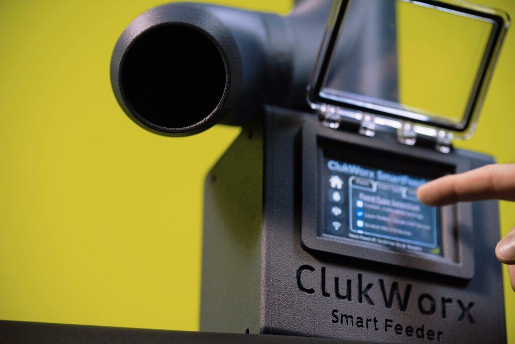
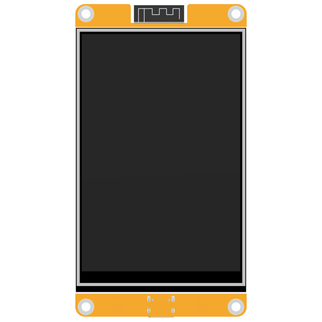
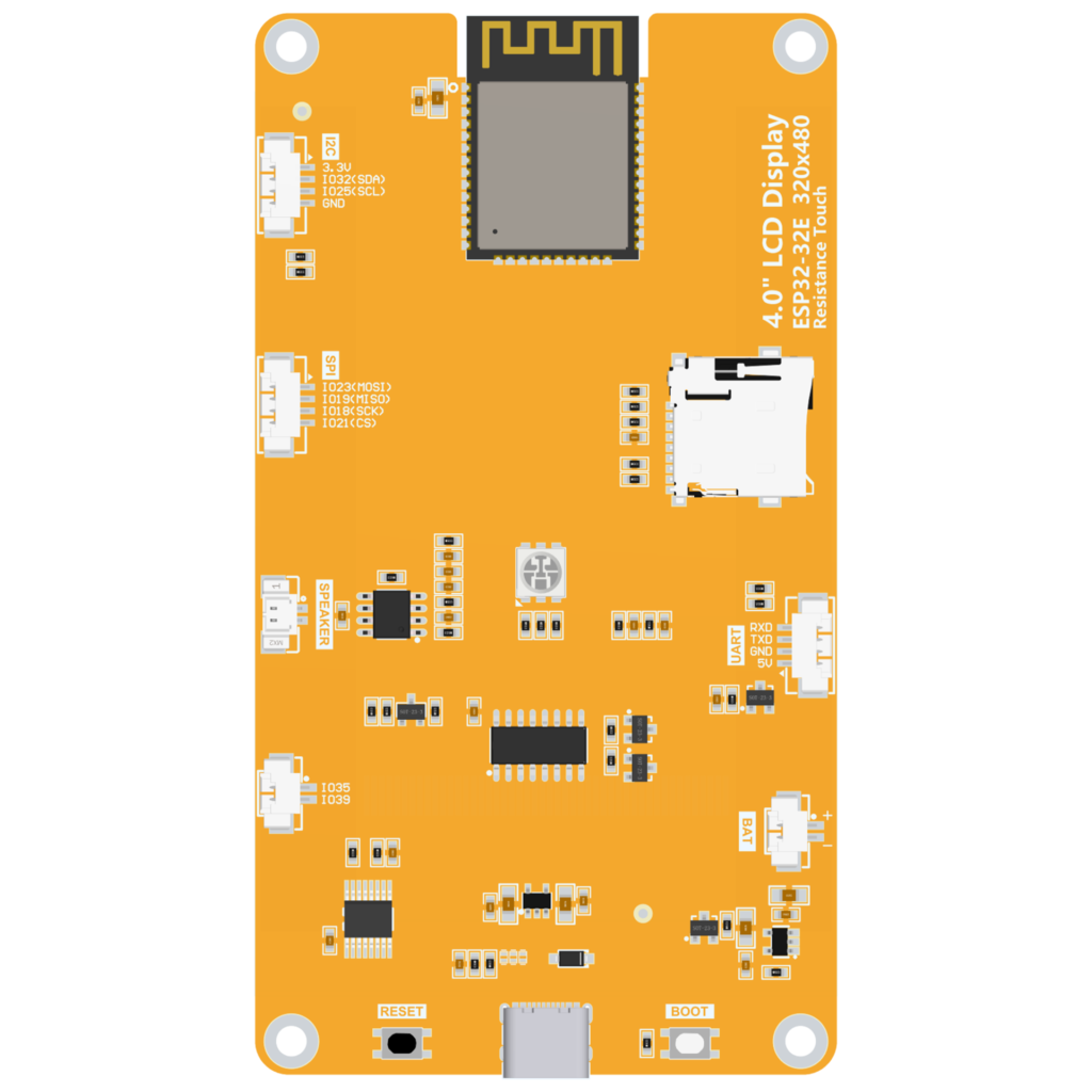
Control System – We want to use community resources to avoid re-inventing wheels available for free. Cheap Yellow Displays (CYDs) are TFT screens with ESP32 chips installed to create an “all-in-one” project board of sorts – which can be used for any project needing micro-control and touch-display. We can use the Arduino Desktop IDE to write our Code, or Visual Studio (I use both depending on the job). This particular system runs on top of ESPHOME firmware which is commonly used in Home Automation applications – I chose this package because it is extremely well documented and allowed for a modern and responsive user interface. The ESP32 will send signals via UART to the SAMD21, which will create the precise signals for the motor via custom stepper motor pulsing algorithms I wrote for this project (sorry Accellstepper Bro’s).
Hardware –
Battery – 660- Amp Hours, 14.4 V , 5A
Buck Converter – 120 V / 12 V – 5A
MCU (the brains) x 2 – (ES3P32 for display and user control, SAMD21 – Seeduino XIAO for all Motor Controls)
Touch Screen – *included in ESP32 MCU
Stepper Motor – Nema 17, 80 N-cm Torque, 2.0 A
Motor Driver – DRV8825 by Texas Instruments
Custom PCB for motor driver and 2nd MCU
Current Monitoring – ACS711/712* (This will be a rough way to graph the current draw of the motor to detect jams and alert me via wifi)
Enclosure – ASA Carbon Fiber (Weather resistant, UV resistant, embedded carbon fiber to prevent warping during “printing”)
Hardware exposed to feed – must be printed in PTEG to avoid issues with food/plastic interactions.
Code
This was y very first ESP32 Project…. so I had many hurdles and re-wrote the full code 3 times prior to settling on ESPHOME as the UI firmware framework. After using the Arduino with TFT_eSPI packages (super simple but not beautiful), and working in the ESPIDF framework (which I found to be quite silly/frustrating when setting up the configuration methods prior to and during code flashes) – ESPHOME offered the best blend of sleek user interface with LVLG and ESPHOME is documented to hell so we have no shortage of experience to learn from. I would recommend ESPHOME for anyone who doesn’t want to become a programmer to build a chicken feeder due to simplicity and the documentation is great. Reach out to me if you are interested and I will likely send you a link to download my source code (which took me approximately 160 hours to hone in even with the help of A.I . tools).
We will be using visual studio to write the yaml (Yet Another Markup Language), ESPHOME.io for all documentation for the UI and Arduino IDE for the SAMD21 to keep both files open at once in different environments if needed.
I will continue to edit this section and further describe the code more as free time allows, but in general we have allowed a user to select feed times, feed amounts, either an interval period or set times to feed, and we calibrate the unit to know the density/flow rate of the chosen feed type. The unit also has current sensing – which I will discuss at a later time with graphs and analysis.
FINAL PRODUCT!
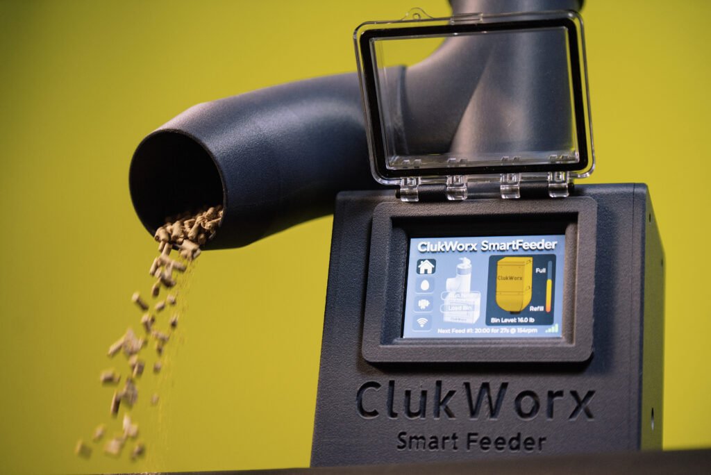
This thing works great, and hasn’t jammed since day 1. We have extreme humidity in Texas – and the touchscreen works great and the internal electronics are still corrosion free after 4 months of fall and winter in my chicken coop. I was thoroughly surprised to find out the feeder even worked during the freeze in January 2026.
If you are interested in building one of you own and would like help, want to purchase print files for this unit with a full hardware BOM and source code, or buying a complete/ready built unit – PLEASE REACH OUT.
This product is Patent Pending, please feel free to reach out for business inquiries.